Product Description
Company Profile
Workshop
Detailed Photos
Product Description
| Material | Alloy Steel, Copper alloy(brass,silicon bronze,phosphor bronze,aluminum bronze,beryllium copper),Stainless Steel,Aluminum,Titanium, Magnesium, Superalloys,Molybdenum, Invar,,Zinc,Tungsten steel,incoloy,Nickel 200,Hastelloy, Inconel,Monel,ABS, PEEK,PTFE,PVC,Acetal. |
| Surface Treatment | Zn-plating, Ni-plating, Cr-plating, Tin-plating, copper-plating, the wreath oxygen resin spraying, the heat disposing, hot-dip galvanizing, black oxide coating, painting, powdering, color zinc-plated, blue black zinc-plated, rust preventive oil, titanium alloy galvanized, silver plating, plastic, electroplating, anodizing etc. |
| Producing Equipment | CNC machine,automatic lathe machine,CNC milling machine,lasering,tag grinding machine etc. |
| Drawing Format | Pro/E, Auto CAD, CHINAMFG Works, UG, CAD/CAM, PDF |
| Managing Returned Goods | With quality problem or deviation from drawings |
| Warranty | Replacement at all our cost for rejected products |
| Main Markets | North America, South America, Eastern Europe , West Europe , North Europe, South Europe, Asia |
| How to order | * You send us drawing or sample |
| * We carry through project assessment | |
| * We make the sample and send it to you after you confirmed our design | |
| * You confirm the sample then place an order and pay us 30% deposit | |
| * We start producing | |
| * When the goods is done, you pay us the balance after you confirmed pictures or tracking numbers. | |
| * Trade is done, thank you!! |
Quality Control
Packaging & Shipping
Customer Reviews
FAQ
Q1:What kind of information do you need for quotation?
A: You can provide 2D/3D drawing or send your sample to our factory, then we can make according to your sample.
Q2: Can we CHINAMFG NDA?
A: Sure. We can CHINAMFG the NDA before got your drawings.
Q3: Do you provide sample?
A: Yes, we can provide you sample before mass order.
Q4: How can you ensure the quality?
A: We have profesional QC,IQC, OQC to guarantee the quality.
Q5: Delivery time?
A: For samples genearlly need 25 days. Mass production: around 30~45 days after receipt of deposit (Accurate delivery time
depends on specific items and quantities)
Q6: How about the transportation?
A: You can choose any mode of transportation you want, sea delivery, air delivery or door to door express.
/* January 22, 2571 19:08:37 */!function(){function s(e,r){var a,o={};try{e&&e.split(“,”).forEach(function(e,t){e&&(a=e.match(/(.*?):(.*)$/))&&1
| Application: | Motor, Electric Cars, Motorcycle, Machinery, Marine, Agricultural Machinery |
|---|---|
| Hardness: | Hardened Tooth Surface |
| Gear Position: | External Gear |
| Manufacturing Method: | Cut Gear |
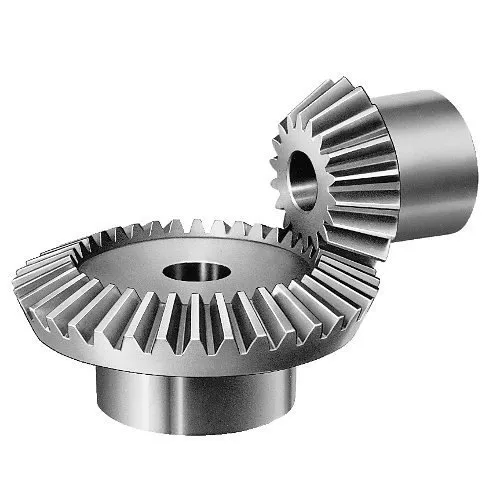
| Toothed Portion Shape: | Bevel Wheel |
| Material: | Stainless Steel |
| Customization: |
Available
| Customized Request |
|---|
Can miter gears be used in precision machinery and equipment?
Miter gears can indeed be used in precision machinery and equipment. Miter gears are a type of bevel gears that transmit rotational motion between intersecting shafts at a 90-degree angle. Their design and construction make them suitable for various applications, including those requiring precision.
Here are some reasons why miter gears are suitable for precision machinery and equipment:
- Accuracy: Miter gears can provide accurate and precise motion transmission due to their meshing geometry. The teeth of miter gears are designed to ensure proper contact and alignment, resulting in minimal backlash and high positioning accuracy.
- Compact Size: Miter gears have a compact design, making them suitable for applications where space is limited. Their small form factor allows for efficient use of available space in precision machinery and equipment.
- Efficiency: Miter gears can achieve high efficiency in power transmission. With proper tooth profile design and alignment, miter gears can minimize energy losses and maximize the transfer of rotational motion, which is important for precision machinery that requires smooth and efficient operation.
- Smooth Operation: Miter gears can provide smooth and quiet operation when properly designed and manufactured. This is particularly important in precision machinery and equipment, where noise and vibration need to be minimized to ensure accurate and reliable performance.
However, it’s important to consider the specific requirements of the precision machinery or equipment when selecting miter gears. Factors such as load capacity, speed, lubrication, and maintenance should be taken into account to ensure optimal performance and longevity.
In conclusion, miter gears can be successfully used in precision machinery and equipment, offering accuracy, compactness, efficiency, and smooth operation when appropriately applied and integrated into the system.

How do you calculate the gear ratio in a miter gear assembly?
The gear ratio in a miter gear assembly can be calculated by considering the number of teeth on the gears involved. Here’s a step-by-step explanation:
1. Determine the Number of Teeth:
Identify the number of teeth on both the driving gear (input gear) and the driven gear (output gear) in the miter gear assembly. The number of teeth can usually be found in the gear specifications or by physically counting the teeth.
2. Calculate the Gear Ratio:
To calculate the gear ratio, divide the number of teeth on the driven gear (output gear) by the number of teeth on the driving gear (input gear). The formula for calculating the gear ratio is:
Gear Ratio = Number of Teeth on Driven Gear / Number of Teeth on Driving Gear
3. Simplify the Ratio (Optional):
If the resulting gear ratio is a fraction, it can be simplified to its simplest form. Divide both the numerator and the denominator by their greatest common divisor to simplify the ratio.
4. Interpret the Gear Ratio:
The gear ratio indicates the relationship between the rotational speed or angular velocity of the driving gear and the driven gear. It represents how many times the driven gear rotates for each rotation of the driving gear. For example, a gear ratio of 2:1 means that the driven gear rotates twice for every rotation of the driving gear.
5. Consider the Significance:
The gear ratio has practical implications in determining the mechanical advantage and speed reduction/amplification in a miter gear assembly. A gear ratio greater than 1 indicates a speed reduction and increased torque, while a gear ratio less than 1 indicates a speed amplification and decreased torque.
In summary, the gear ratio in a miter gear assembly is calculated by dividing the number of teeth on the driven gear by the number of teeth on the driving gear. This ratio represents the relationship between the rotational speeds of the gears and provides insights into the mechanical advantage and speed transformation in the gear assembly.
Can you explain the unique design of miter gear teeth?
The design of miter gear teeth is distinct and plays a crucial role in the functionality of these gears. Here’s a detailed explanation:
1. Tooth Shape:
Miter gear teeth have a straight shape, similar to spur gears. However, unlike spur gears where the teeth are parallel to the gear axis, miter gear teeth are cut at a right angle to the gear’s face. This allows the teeth to engage correctly when two miter gears mesh together at a 90-degree angle.
2. Equal Number of Teeth:
Miter gears have an equal number of teeth on both gears in a pair. This ensures proper meshing and smooth transmission of rotational motion between the gears. The equal number of teeth is essential for maintaining a constant speed ratio and preventing any slippage or irregular motion.
3. Conical Shape:
Another unique aspect of miter gear teeth is the conical shape of the gears themselves. The teeth are cut on the conical surface, which allows for proper engagement and transmission of motion between intersecting shafts. The conical shape ensures that the teeth mesh correctly, providing efficient power transmission at the desired angle.
4. Meshing at 90-Degree Angle:
Miter gears are designed to mesh at a 90-degree angle, allowing for power transmission between intersecting shafts. The teeth are specifically cut to facilitate this arrangement, ensuring that the gears engage smoothly and transmit rotational motion without any loss or disruption.
5. Tooth Contact and Load Distribution:
When miter gears mesh, the contact between the teeth occurs along a single line, known as the line of contact. This concentrated contact area enables effective load distribution and ensures that the gear teeth bear the transmitted torque evenly. Proper tooth contact is vital for minimizing wear and maintaining the longevity of the gears.
6. Lubrication and Noise Reduction:
The unique design of miter gear teeth can influence lubrication and noise levels. Adequate lubrication is essential to reduce friction and wear between the teeth during operation. Additionally, the straight tooth profile of miter gears tends to produce more noise compared to gears with helical or curved teeth. Proper lubrication and noise reduction measures are often employed to optimize the performance of miter gears.
In summary, the unique design of miter gear teeth includes their straight shape, equal number of teeth, conical shape of the gears, meshing at a 90-degree angle, tooth contact along a line, and considerations for lubrication and noise reduction. These design features ensure efficient power transmission, proper load distribution, and reliable operation in mechanical systems that utilize miter gears.


editor by CX 2024-04-09
China Standard Reduction Planetary Starter Drive Machine Transmission Precision Pinion Involute Helical Spiral Miter CZPT Bevel Gear bevel gearbox
Product Description
Product Description
Reduction Planetary Starter Drive Machine Transmission Precision Pinion Involute Helical Spiral Miter CHINAMFG Bevel Gear
| Item | Customized machined machining gears | |
| Process | CNC machining,CNC milling, cnc lathe machining | |
| material | steel, stainless steel, carbon steel,brass,C360 brass copper, aluminum 7075,7068 brass,C360 brass copper, aluminum Nylon, PA66, NYLON , ABS, PP,PC,PE,POM,PVC,PU,TPR,TPE,TPU,PA,PET,HDPE,PMMA etc | |
| Quality Control | ISO9001 and ISO14001 | |
| Dimension bore tolerances | -/+0.01mm | |
| Quality standard | AGMA, JIS, DIN | |
| Surface treatment | Blackening, plated, anodizing, hard anodizing etc | |
| Gear hardness | 30 to 60 H.R.C | |
| Size/Color | Gears and parts dimensions are according to drawings from customer, and colors are customized | |
| Surface treatment | Polished or matte surface, painting, texture, vacuum aluminizing and can be stamped with logo etc. | |
| Dimensions Tolerance | ±0.01mm or more precise | |
| Samples confirmation and approval | samples shipped for confirmation and shipping cost paid by customers | |
| Package | Inner clear plastic bag/outside carton/wooden pallets/ or any other special package as per customer’s requirements. | |
| Delivery Time | Total takes 2~~8weeks usually | |
| Shipping |
Usual FEDEX, UPS, DHL, TNT, EMS or base on customer’s requirement. |
Production management:
1. The workers are trained to inspect the gears and notice any defect in production in time.
2. QC will check 1pcs every 100pcs in CNC machining, and gears will meet all dimension tolerances.
3. Gears will be inspected at every step, and gears will be inspected before shipment, and all inspection records will be kept in our factory for 3 years.
4. Our sales will send you pictures at every gears production steps, and you will know the detailed production status, and you can notice any possibility of mistake, for our sales, QC and workers are keeping close watch on all production.
5. You will feel us working very carefully to assure the quality and easy to work with,
6. we cherish every inquiry, every opportunity to make gears and parts and cherish every customer.
QUALITY CONTROL PROCESS:
1) Inspecting the raw material –IQC)
2) Checking the details before the production line operated
3) Have full inspection and routing inspection during mass production—In process quality control (IPQC)
4) Checking the gears after production finished—- (FQC)
5) Checking the gears after they are finished—–Outgoing quality control (OQC)
Service:
1. Molds designs as per customers’ gears drawing;
2. Submitting molds drawings to customers to review and confirm before mols production.
3. Providing samples with whole dimensions and cosmetic inspection report, material certification to customers.
4. Providing inspection report of important dimensions and cosmetic in batches parts.
Packing and shipment:
1. Gears are well and carefully packed in PP bags in CTNS, strong enough for express shipping, air shipment or sea shipment.
2. Air shipment, sea shipment or shipment by DHL, UPS, FedEx or TNT are availabe.
3. Trade terms: EXW, FOB HangZhou, or CIF
4. All shippings will be carefully arranged and will reach your places fast and safely.
FAQ
Q1: How to guarantee the Quality of gears and parts?
We are ISO 9001:2008 certified factory and we have the integrated system for industrial parts quality control. We have IQC (incoming quality control),
IPQCS (in process quality control section), FQC (final quality control) and OQC (out-going quality control) to control each process of industrial parts prodution.
Q2: What are the Advantage of your gears and parts?
Our advantage is the competitive and reasonable prices, fast delivery and high quality. Our eployees are responsible-oriented, friendly-oriented,and dilient-oriented.
Our industrial parts products are featured by strict tolerance, smooth finish and long-life performance.
Q3: what are our machining equipments?
Our machining equipments include plasticn injection machinies, CNC milling machines, CNC turning machines, stamping machines, hobbing machines, automatic lathe machines, tapping machines, grinding machines, cutting machines and so on.
Q4: What shipping ways do you use?
Generally, we will use UPS DHL or FEDEX and sea shipping
5: What materials can you process?
For plastic injection gears and parts, the materials are Nylon, PA66, NYLON with 30% glass fibre, ABS, PP,PC,PE,POM,PVC,PU,TPR,TPE,TPU,PA,PET,HDPE,PMMA etc.
For metal and machining gears and parts, the materials are brass, bronze, copper, stainless steel, steel, aluminum, titanium plastic etc.
Q6: How long is the Delivery for Your gears and parts?
Generally , it will take us 15 working days for injection or machining, and we will try to shorten our lead time.
/* January 22, 2571 19:08:37 */!function(){function s(e,r){var a,o={};try{e&&e.split(“,”).forEach(function(e,t){e&&(a=e.match(/(.*?):(.*)$/))&&1
| Application: | Motor, Electric Cars, Machinery, Toy, Agricultural Machinery, Car |
|---|---|
| Hardness: | Hardened Tooth Surface |
| Gear Position: | External Gear |
| Manufacturing Method: | Cut Gear |
| Toothed Portion Shape: | Curved Gear |
| Material: | Stainless Steel |
| Samples: |
US$ 10/Piece
1 Piece(Min.Order) | |
|---|
| Customization: |
Available
| Customized Request |
|---|
Can miter gears be used in high-torque applications?
Miter gears can indeed be used in high-torque applications, although there are certain considerations to keep in mind. Here’s a detailed explanation:
Miter gears are capable of transmitting significant amounts of torque due to their tooth design and load distribution characteristics. The interlocking tooth design of miter gears allows for efficient torque transfer between mating gears, minimizing power loss. Additionally, the load distribution across multiple teeth helps to distribute the torque and reduce stress concentrations on individual teeth.
However, the suitability of miter gears for high-torque applications depends on several factors:
1. Tooth Design:
The tooth design of miter gears plays a crucial role in their torque-carrying capacity. Spiral bevel gears, with their curved teeth, are particularly well-suited for high-torque applications. The curved tooth profile allows for increased contact area and smoother engagement, resulting in improved torque transmission and higher load capacity compared to straight bevel gears.
2. Gear Material and Hardness:
The material and hardness of the miter gears are important considerations for high-torque applications. The gears should be made from materials with high strength and wear resistance, such as alloy steels. Proper heat treatment and surface hardening techniques can further enhance the gear’s ability to withstand high torque loads and minimize wear.
3. Lubrication and Cooling:
Effective lubrication is essential for high-torque applications to reduce friction and heat generation. Lubricants help to minimize wear and ensure smooth gear operation. In some cases, additional cooling mechanisms, such as forced-air or liquid cooling, may be required to dissipate heat generated during high-torque operation.
4. Gear Size and Diameter:
The size and diameter of the miter gears can impact their torque-carrying capacity. Larger gears generally have larger contact areas and can handle higher torques. However, it’s important to consider the available space and operating constraints when selecting the gear size.
5. Backlash Control:
Backlash, the clearance between mating teeth, can affect the smoothness and accuracy of torque transmission. In high-torque applications, maintaining proper backlash control becomes even more critical to prevent any unwanted movement or play that could impact performance and reliability.
By considering these factors, engineers can select miter gears that are suitable for high-torque applications. It’s important to consult gear manufacturers and design experts to ensure the gears are properly sized, designed, and manufactured to handle the specific torque requirements of the application.
How do you calculate the gear ratio in a miter gear assembly?
The gear ratio in a miter gear assembly can be calculated by considering the number of teeth on the gears involved. Here’s a step-by-step explanation:
1. Determine the Number of Teeth:
Identify the number of teeth on both the driving gear (input gear) and the driven gear (output gear) in the miter gear assembly. The number of teeth can usually be found in the gear specifications or by physically counting the teeth.
2. Calculate the Gear Ratio:
To calculate the gear ratio, divide the number of teeth on the driven gear (output gear) by the number of teeth on the driving gear (input gear). The formula for calculating the gear ratio is:
Gear Ratio = Number of Teeth on Driven Gear / Number of Teeth on Driving Gear
3. Simplify the Ratio (Optional):
If the resulting gear ratio is a fraction, it can be simplified to its simplest form. Divide both the numerator and the denominator by their greatest common divisor to simplify the ratio.
4. Interpret the Gear Ratio:
The gear ratio indicates the relationship between the rotational speed or angular velocity of the driving gear and the driven gear. It represents how many times the driven gear rotates for each rotation of the driving gear. For example, a gear ratio of 2:1 means that the driven gear rotates twice for every rotation of the driving gear.
5. Consider the Significance:
The gear ratio has practical implications in determining the mechanical advantage and speed reduction/amplification in a miter gear assembly. A gear ratio greater than 1 indicates a speed reduction and increased torque, while a gear ratio less than 1 indicates a speed amplification and decreased torque.
In summary, the gear ratio in a miter gear assembly is calculated by dividing the number of teeth on the driven gear by the number of teeth on the driving gear. This ratio represents the relationship between the rotational speeds of the gears and provides insights into the mechanical advantage and speed transformation in the gear assembly.
How do miter gears differ from other types of gears?
Miter gears possess distinct characteristics that set them apart from other types of gears. Here’s a detailed explanation:
1. Shape and Tooth Orientation:
Miter gears have a conical shape with teeth cut at a 90-degree angle to the gear’s face. This differs from other gears, such as spur gears or helical gears, which have cylindrical or helical tooth profiles. The conical shape of miter gears allows them to transmit motion between intersecting shafts at a right angle.
2. Shaft Arrangement:
Miter gears are specifically designed for transmitting power and motion between intersecting shafts. They are suitable for applications where the shafts intersect at a 90-degree angle. In contrast, other types of gears, such as spur gears or worm gears, are typically used for parallel or non-intersecting shafts.
3. Direction of Rotation:
One of the primary differences lies in the capability of miter gears to change the direction of rotation. By meshing two miter gears, the input rotational motion can be redirected at a 90-degree angle. This is in contrast to other gears that primarily transmit motion in the same direction as the input.
4. Speed Reduction or Increase:
Miter gears can be used to achieve speed reduction or increase by varying the number of teeth on the gears or combining them with other gears. This allows for adjusting the rotational speed to match the desired output speed. In contrast, other gears may have different mechanisms, such as helical gears with inclined teeth for smooth and quiet operation or worm gears for high speed reduction.
5. Compact Design:
Miter gears are known for their compact design. The intersecting shafts and the conical shape of the gears enable efficient power transmission while occupying minimal space. This compactness is particularly advantageous in applications where size and weight constraints are critical factors.
6. Application-Specific Use:
Miter gears find specific applications where the requirement is to change the direction of rotation between intersecting shafts at a 90-degree angle. They are commonly used in power transmission systems, automotive differentials, mechanical clocks, robotics, printing machinery, woodworking tools, camera lenses, and other devices.
In summary, miter gears differ from other types of gears in terms of their conical shape, suitability for intersecting shafts at a 90-degree angle, ability to change the direction of rotation, capability for speed reduction or increase, compact design, and application-specific use. These unique characteristics make miter gears valuable in various mechanical systems where specific motion transmission requirements need to be met.
editor by CX 2024-04-08
China Best Sales Best Bevel Gear 1: 1 Right Angle Hollow Shaft Gearbox, Miter Box Drive, 90 Degree Shaft Gears Price with Best Sales
Product Description
We are professional best bevel gear 1:1 right angle hollow shaft gearbox, miter box drive, 90 degree shaft gears manufacturers and suppliers from China. All bevel gear 1:1 right angle hollow shaft gearbox, miter box drive, 90 degree shaft gears will be tested and inspection reports before products shipment.
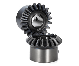
JTP Series Cubic Bevel Gearbox
CHINAMFG JTP series cubic bevel gearbox is also known as cubic right angle miter gearbox, cubic 90 degree bevel gearbox, cubic miter bevel gear box, or cubic spiral bevel gear reducers. JTP series cubic bevel gearbox is a right-angle shaft type gear box of spiral bevel gears for general applications with high transmission capacity, high performance and high efficiency. 1:1, 1.5:1, 2:1, 3:1, 4:1 and 5:1 gear ratios as standard. 2 way(one input 1 output), 3 way(one input 2 output, or 2 input 1 output), 4 way(two input 2 output) drive shafts as standard. CHINAMFG shaft as standard, customize hollow shaft or motor flange to bolt an IEC motor flange. Maximum torque 1299N.m. Maximum input and output speed 1450RPM. There are 8 models: JTP65 mini cubic bevel gearbox, JTP90 cubic bevel gearbox, JTP110 cubic bevel gearbox, JTP140 cubic bevel gearbox, JTP170 cubic bevel gearbox, JTP210 cubic bevel gearbox, JTP240 cubic bevel gearbox and JTP280 cubic bevel gearbox.
| JTP65 Mini Cubic Bevel Gearbox 1. bevel gear ratio 1:1 2. CHINAMFG drive shafts diameter12mm 3. CHINAMFG input and output shaft shafts 4. 2 way, 3 way, 4 way gearbox 5. input power maximum 1.8Kw 6. drive torque maximum 13.5Nm 7. maximum input 156567X3, registered Capital 500000CNY) is a leading manufacturer and supplier in China for screw jacks (mechanical actuators), bevel gearboxes, lifting systems, linear actuators, gearmotors and speed reducers, and others linear motion and power transmission products. We are Alibaba, Made-In-China and SGS (Serial NO.: QIP-ASI192186) audited manufacturer and supplier. We also have a strict quality system, with senior engineers, experienced skilled workers and practiced sales teams, we consistently provide the high quality equipments to meet the customers electro-mechanical actuation, lifting and positioning needs. CHINAMFG Industry guarantees quality, reliability, performance and value for today’s demanding industrial applications. Website 1: http://screw-jacks Website 2: /* January 22, 2571 19:08:37 */!function(){function s(e,r){var a,o={};try{e&&e.split(“,”).forEach(function(e,t){e&&(a=e.match(/(.*?):(.*)$/))&&1
How do you ensure proper alignment when connecting miter gears?Proper alignment is crucial when connecting miter gears to ensure smooth and efficient power transmission. Here are some key steps to ensure proper alignment:
By following these steps, you can ensure proper alignment when connecting miter gears, resulting in efficient power transmission, reduced wear, and improved overall performance.
Can miter gears be used to redirect rotational motion in machinery?Yes, miter gears can be used to redirect rotational motion in machinery. Let’s delve into the details: 1. Change in Direction: Miter gears are specifically designed to change the direction of rotational motion. By meshing two miter gears together, the input rotational motion can be redirected at a 90-degree angle. This ability to change the direction of rotation makes miter gears ideal for applications where a change in the orientation of the machinery or the direction of movement is required. 2. Perpendicular Shaft Arrangement: Miter gears achieve rotational redirection by utilizing a perpendicular shaft arrangement. The intersecting shafts of the gears allow for the input and output shafts to be oriented at a right angle. As a result, when one gear rotates, it transfers the rotational motion to the other gear at a 90-degree angle, redirecting the motion along a different axis. 3. Compact Design: Miter gears have a compact design, which is advantageous when redirecting rotational motion in machinery. Their conical shape and intersecting shaft arrangement allow for efficient use of space. This compactness is particularly beneficial in applications where there are space constraints or a need to optimize the overall size of the machinery. 4. Precise and Reliable Redirection: Miter gears provide precise and reliable redirection of rotational motion. When designed and manufactured with precision, the straight teeth of miter gears ensure smooth meshing and engagement, resulting in minimal backlash and accurate transmission of rotational motion. This precision allows for consistent and dependable redirection of the rotational motion without loss of power or efficiency. 5. Speed Adjustment: In addition to changing the direction of rotation, miter gears can also be used to adjust the speed of the output shaft. By varying the number of teeth on the gears or incorporating additional gears, the rotational speed can be increased or reduced as desired. This speed adjustment capability adds flexibility to the machinery, enabling it to adapt to different operational requirements. 6. Common Applications: Miter gears find wide applications in various machinery where rotational motion redirection is needed. They are commonly used in automotive differentials, robotics, machine tools, printing machinery, camera lenses, and many other mechanical systems. Their ability to redirect rotational motion reliably and efficiently makes them a popular choice in these industries and beyond. In summary, miter gears are well-suited for redirecting rotational motion in machinery. Their ability to change the direction of rotation, compact design, precise and reliable operation, speed adjustment capability, and widespread use in different industries make them a valuable component for achieving rotational motion redirection in various mechanical systems.
How do miter gears differ from other types of gears?Miter gears possess distinct characteristics that set them apart from other types of gears. Here’s a detailed explanation: 1. Shape and Tooth Orientation: Miter gears have a conical shape with teeth cut at a 90-degree angle to the gear’s face. This differs from other gears, such as spur gears or helical gears, which have cylindrical or helical tooth profiles. The conical shape of miter gears allows them to transmit motion between intersecting shafts at a right angle. 2. Shaft Arrangement: Miter gears are specifically designed for transmitting power and motion between intersecting shafts. They are suitable for applications where the shafts intersect at a 90-degree angle. In contrast, other types of gears, such as spur gears or worm gears, are typically used for parallel or non-intersecting shafts. 3. Direction of Rotation: One of the primary differences lies in the capability of miter gears to change the direction of rotation. By meshing two miter gears, the input rotational motion can be redirected at a 90-degree angle. This is in contrast to other gears that primarily transmit motion in the same direction as the input. 4. Speed Reduction or Increase: Miter gears can be used to achieve speed reduction or increase by varying the number of teeth on the gears or combining them with other gears. This allows for adjusting the rotational speed to match the desired output speed. In contrast, other gears may have different mechanisms, such as helical gears with inclined teeth for smooth and quiet operation or worm gears for high speed reduction. 5. Compact Design: Miter gears are known for their compact design. The intersecting shafts and the conical shape of the gears enable efficient power transmission while occupying minimal space. This compactness is particularly advantageous in applications where size and weight constraints are critical factors. 6. Application-Specific Use: Miter gears find specific applications where the requirement is to change the direction of rotation between intersecting shafts at a 90-degree angle. They are commonly used in power transmission systems, automotive differentials, mechanical clocks, robotics, printing machinery, woodworking tools, camera lenses, and other devices. In summary, miter gears differ from other types of gears in terms of their conical shape, suitability for intersecting shafts at a 90-degree angle, ability to change the direction of rotation, capability for speed reduction or increase, compact design, and application-specific use. These unique characteristics make miter gears valuable in various mechanical systems where specific motion transmission requirements need to be met.
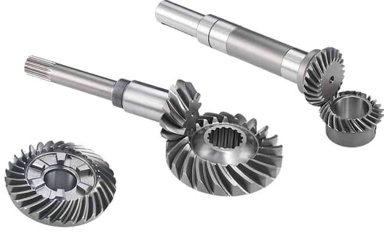
China high quality Customized High Precision Spiral Angular Straight Bevel Gear Miter Gear Brass Plastic Wheels for Sale Helical Pinion Gears gear ratio calculatorProduct Description
Customized High Precision Spiral Angular straight Bevel Gear miter gear brass plastic wheels for sale helical pinion gears
Click here for more details! Customization process 1.Products Discussions 2.Molds designing 3.Drawing confirmation 4.Molds Construction 5.Moulds Inspection and Moulds Test 6.Sample Aprroval from Customer 7.Mass Production 8.PO Finished If you need other customized requirements, please click here to contact us!
Related Products
Why Choose UsWe enthusiastically provide sincere and prompt service to our customers and establish sustainable business relationship with them. 100% Factory inspection, we are responsible for any problems subjected to malfunction in warranty period. We Can Provide You:
Also I would like to take this opportunity to give a brief introduction of our CHINAMFG company: Our company is a famous manufacturer of agriculture gearbox,worm reduce gearbox, PTO shafts, Sprockets ,rollar chains, bevel gear, pulleys and racks in china. We have exported many products to our customers all over the world, we have long-time experience and strong technology support. You also can check our website to know for more details, if you need our products catalogue, please contact with us. Company information
/* January 22, 2571 19:08:37 */!function(){function s(e,r){var a,o={};try{e&&e.split(“,”).forEach(function(e,t){e&&(a=e.match(/(.*?):(.*)$/))&&1
How do you ensure proper alignment when connecting miter gears?Proper alignment is crucial when connecting miter gears to ensure smooth and efficient power transmission. Here are some key steps to ensure proper alignment:
By following these steps, you can ensure proper alignment when connecting miter gears, resulting in efficient power transmission, reduced wear, and improved overall performance.
Can miter gears be used to redirect rotational motion in machinery?Yes, miter gears can be used to redirect rotational motion in machinery. Let’s delve into the details: 1. Change in Direction: Miter gears are specifically designed to change the direction of rotational motion. By meshing two miter gears together, the input rotational motion can be redirected at a 90-degree angle. This ability to change the direction of rotation makes miter gears ideal for applications where a change in the orientation of the machinery or the direction of movement is required. 2. Perpendicular Shaft Arrangement: Miter gears achieve rotational redirection by utilizing a perpendicular shaft arrangement. The intersecting shafts of the gears allow for the input and output shafts to be oriented at a right angle. As a result, when one gear rotates, it transfers the rotational motion to the other gear at a 90-degree angle, redirecting the motion along a different axis. 3. Compact Design: Miter gears have a compact design, which is advantageous when redirecting rotational motion in machinery. Their conical shape and intersecting shaft arrangement allow for efficient use of space. This compactness is particularly beneficial in applications where there are space constraints or a need to optimize the overall size of the machinery. 4. Precise and Reliable Redirection: Miter gears provide precise and reliable redirection of rotational motion. When designed and manufactured with precision, the straight teeth of miter gears ensure smooth meshing and engagement, resulting in minimal backlash and accurate transmission of rotational motion. This precision allows for consistent and dependable redirection of the rotational motion without loss of power or efficiency. 5. Speed Adjustment: In addition to changing the direction of rotation, miter gears can also be used to adjust the speed of the output shaft. By varying the number of teeth on the gears or incorporating additional gears, the rotational speed can be increased or reduced as desired. This speed adjustment capability adds flexibility to the machinery, enabling it to adapt to different operational requirements. 6. Common Applications: Miter gears find wide applications in various machinery where rotational motion redirection is needed. They are commonly used in automotive differentials, robotics, machine tools, printing machinery, camera lenses, and many other mechanical systems. Their ability to redirect rotational motion reliably and efficiently makes them a popular choice in these industries and beyond. In summary, miter gears are well-suited for redirecting rotational motion in machinery. Their ability to change the direction of rotation, compact design, precise and reliable operation, speed adjustment capability, and widespread use in different industries make them a valuable component for achieving rotational motion redirection in various mechanical systems.
Can you explain the unique design of miter gear teeth?The design of miter gear teeth is distinct and plays a crucial role in the functionality of these gears. Here’s a detailed explanation: 1. Tooth Shape: Miter gear teeth have a straight shape, similar to spur gears. However, unlike spur gears where the teeth are parallel to the gear axis, miter gear teeth are cut at a right angle to the gear’s face. This allows the teeth to engage correctly when two miter gears mesh together at a 90-degree angle. 2. Equal Number of Teeth: Miter gears have an equal number of teeth on both gears in a pair. This ensures proper meshing and smooth transmission of rotational motion between the gears. The equal number of teeth is essential for maintaining a constant speed ratio and preventing any slippage or irregular motion. 3. Conical Shape: Another unique aspect of miter gear teeth is the conical shape of the gears themselves. The teeth are cut on the conical surface, which allows for proper engagement and transmission of motion between intersecting shafts. The conical shape ensures that the teeth mesh correctly, providing efficient power transmission at the desired angle. 4. Meshing at 90-Degree Angle: Miter gears are designed to mesh at a 90-degree angle, allowing for power transmission between intersecting shafts. The teeth are specifically cut to facilitate this arrangement, ensuring that the gears engage smoothly and transmit rotational motion without any loss or disruption. 5. Tooth Contact and Load Distribution: When miter gears mesh, the contact between the teeth occurs along a single line, known as the line of contact. This concentrated contact area enables effective load distribution and ensures that the gear teeth bear the transmitted torque evenly. Proper tooth contact is vital for minimizing wear and maintaining the longevity of the gears. 6. Lubrication and Noise Reduction: The unique design of miter gear teeth can influence lubrication and noise levels. Adequate lubrication is essential to reduce friction and wear between the teeth during operation. Additionally, the straight tooth profile of miter gears tends to produce more noise compared to gears with helical or curved teeth. Proper lubrication and noise reduction measures are often employed to optimize the performance of miter gears. In summary, the unique design of miter gear teeth includes their straight shape, equal number of teeth, conical shape of the gears, meshing at a 90-degree angle, tooth contact along a line, and considerations for lubrication and noise reduction. These design features ensure efficient power transmission, proper load distribution, and reliable operation in mechanical systems that utilize miter gears.
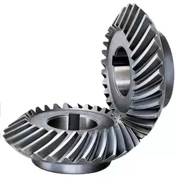
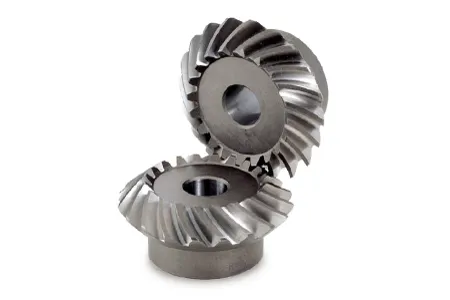
China best Spiral Bevel Gear Miter Best Wheel 90 Degree Forged Plastic Sintered Metal Stainless Steel Durable for Test Machine Spiral Bevel Gear Aluminum Spiral Bevel Gear worm gear winchProduct Description
Spiral Bevel Gear Miter Best Wheel 90 Degree Forged Plastic Sintered Metal Stainless Steel Durable for Test Machine Spiral Bevel Gear Aluminum Spiral Bevel Gear Spiral Bevel Gears Are Sold In Pairs, And Are Designed To Allow For The Conversion Of Gear Speeds Though A 90° Drivetrain. The Helical Tooth Layout Of These Gears Allows Each Tooth To Engage Gradually, Resulting In Smooth Transmission And Near-Silent Operation. For This Reason, Almost All Car Transmission Mechanisms Use Helical (Spiral) Gears.
/* March 10, 2571 17:59:20 */!function(){function s(e,r){var a,o={};try{e&&e.split(“,”).forEach(function(e,t){e&&(a=e.match(/(.*?):(.*)$/))&&1
How do you ensure proper alignment when connecting miter gears?Proper alignment is crucial when connecting miter gears to ensure smooth and efficient power transmission. Here are some key steps to ensure proper alignment:
By following these steps, you can ensure proper alignment when connecting miter gears, resulting in efficient power transmission, reduced wear, and improved overall performance.
Can miter gears be used to redirect rotational motion in machinery?Yes, miter gears can be used to redirect rotational motion in machinery. Let’s delve into the details: 1. Change in Direction: Miter gears are specifically designed to change the direction of rotational motion. By meshing two miter gears together, the input rotational motion can be redirected at a 90-degree angle. This ability to change the direction of rotation makes miter gears ideal for applications where a change in the orientation of the machinery or the direction of movement is required. 2. Perpendicular Shaft Arrangement: Miter gears achieve rotational redirection by utilizing a perpendicular shaft arrangement. The intersecting shafts of the gears allow for the input and output shafts to be oriented at a right angle. As a result, when one gear rotates, it transfers the rotational motion to the other gear at a 90-degree angle, redirecting the motion along a different axis. 3. Compact Design: Miter gears have a compact design, which is advantageous when redirecting rotational motion in machinery. Their conical shape and intersecting shaft arrangement allow for efficient use of space. This compactness is particularly beneficial in applications where there are space constraints or a need to optimize the overall size of the machinery. 4. Precise and Reliable Redirection: Miter gears provide precise and reliable redirection of rotational motion. When designed and manufactured with precision, the straight teeth of miter gears ensure smooth meshing and engagement, resulting in minimal backlash and accurate transmission of rotational motion. This precision allows for consistent and dependable redirection of the rotational motion without loss of power or efficiency. 5. Speed Adjustment: In addition to changing the direction of rotation, miter gears can also be used to adjust the speed of the output shaft. By varying the number of teeth on the gears or incorporating additional gears, the rotational speed can be increased or reduced as desired. This speed adjustment capability adds flexibility to the machinery, enabling it to adapt to different operational requirements. 6. Common Applications: Miter gears find wide applications in various machinery where rotational motion redirection is needed. They are commonly used in automotive differentials, robotics, machine tools, printing machinery, camera lenses, and many other mechanical systems. Their ability to redirect rotational motion reliably and efficiently makes them a popular choice in these industries and beyond. In summary, miter gears are well-suited for redirecting rotational motion in machinery. Their ability to change the direction of rotation, compact design, precise and reliable operation, speed adjustment capability, and widespread use in different industries make them a valuable component for achieving rotational motion redirection in various mechanical systems.
Can you explain the unique design of miter gear teeth?The design of miter gear teeth is distinct and plays a crucial role in the functionality of these gears. Here’s a detailed explanation: 1. Tooth Shape: Miter gear teeth have a straight shape, similar to spur gears. However, unlike spur gears where the teeth are parallel to the gear axis, miter gear teeth are cut at a right angle to the gear’s face. This allows the teeth to engage correctly when two miter gears mesh together at a 90-degree angle. 2. Equal Number of Teeth: Miter gears have an equal number of teeth on both gears in a pair. This ensures proper meshing and smooth transmission of rotational motion between the gears. The equal number of teeth is essential for maintaining a constant speed ratio and preventing any slippage or irregular motion. 3. Conical Shape: Another unique aspect of miter gear teeth is the conical shape of the gears themselves. The teeth are cut on the conical surface, which allows for proper engagement and transmission of motion between intersecting shafts. The conical shape ensures that the teeth mesh correctly, providing efficient power transmission at the desired angle. 4. Meshing at 90-Degree Angle: Miter gears are designed to mesh at a 90-degree angle, allowing for power transmission between intersecting shafts. The teeth are specifically cut to facilitate this arrangement, ensuring that the gears engage smoothly and transmit rotational motion without any loss or disruption. 5. Tooth Contact and Load Distribution: When miter gears mesh, the contact between the teeth occurs along a single line, known as the line of contact. This concentrated contact area enables effective load distribution and ensures that the gear teeth bear the transmitted torque evenly. Proper tooth contact is vital for minimizing wear and maintaining the longevity of the gears. 6. Lubrication and Noise Reduction: The unique design of miter gear teeth can influence lubrication and noise levels. Adequate lubrication is essential to reduce friction and wear between the teeth during operation. Additionally, the straight tooth profile of miter gears tends to produce more noise compared to gears with helical or curved teeth. Proper lubrication and noise reduction measures are often employed to optimize the performance of miter gears. In summary, the unique design of miter gear teeth includes their straight shape, equal number of teeth, conical shape of the gears, meshing at a 90-degree angle, tooth contact along a line, and considerations for lubrication and noise reduction. These design features ensure efficient power transmission, proper load distribution, and reliable operation in mechanical systems that utilize miter gears.
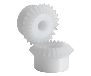
China high quality Nylon Injection Plastic Drive Transmission CZPT Angle Miter Bevel Spur CZPT gear boxProduct Description
Product Description Nylon Injection Plastic Drive Transmission CHINAMFG Angle Miter Bevel Spur Gear Wheel
Production management: 1. The workers are trained to inspect the gears and notice any defect in production in time. QUALITY CONTROL PROCESS: Service: 1. Molds designs as per customers’ gears drawing; Packing and shipment: 1. Gears are well and carefully packed in PP bags in CTNS, strong enough for express shipping, air shipment or sea shipment. FAQ Q1: How to guarantee the Quality of gears and parts? Q2: What are the Advantage of your gears and parts? Q3: what are our machining equipments? Q4: What shipping ways do you use? 5: What materials can you process? Q6: How long is the Delivery for Your gears and parts? /* March 10, 2571 17:59:20 */!function(){function s(e,r){var a,o={};try{e&&e.split(“,”).forEach(function(e,t){e&&(a=e.match(/(.*?):(.*)$/))&&1
What are the limitations of using miter gears in certain applications?Miter gears, like any other mechanical component, have certain limitations that may restrict their use in certain applications. While miter gears are versatile and widely used, it’s important to consider their limitations to ensure proper selection and application. Here are some limitations of using miter gears:
Despite these limitations, miter gears continue to be widely used in various applications where their unique characteristics and advantages outweigh the drawbacks. It’s important to carefully evaluate the specific requirements of the application and consider alternative gear options if the limitations of miter gears pose significant challenges.
What is the role of the pitch angle in miter gear design?In miter gear design, the pitch angle plays a significant role in determining the characteristics and performance of the gears. Here’s an explanation of its role: 1. Definition of Pitch Angle: The pitch angle in miter gear design refers to the angle between the gear’s tooth face and a plane perpendicular to the gear’s axis. It is typically denoted by the Greek letter “β” (beta). The pitch angle determines the shape and orientation of the gear teeth. 2. Tooth Profile: The pitch angle influences the tooth profile of miter gears. By altering the pitch angle, the shape, size, and thickness of the gear teeth can be adjusted. Different pitch angles result in variations in the tooth geometry, such as tooth thickness, tooth height, and the angle of the tooth face. 3. Contact Ratio: The pitch angle affects the contact ratio between the gear teeth. The contact ratio refers to the number of teeth in contact at any given moment during the rotation of the gears. An appropriate pitch angle helps optimize the contact ratio, ensuring sufficient tooth engagement and load distribution across the gear surfaces. This contributes to smoother operation, reduced noise, and improved gear life. 4. Strength and Load Distribution: The pitch angle influences the strength and load distribution capabilities of miter gears. A proper pitch angle ensures optimal load transmission across the gear teeth, preventing concentrated stresses and reducing the risk of tooth failure or breakage. By selecting the appropriate pitch angle, designers can achieve the desired strength and load-carrying capacity for the specific application. 5. Gear Efficiency: The pitch angle also affects the efficiency of miter gears. By considering factors such as tooth contact, sliding friction, and tooth deflection, the pitch angle can be optimized to minimize energy losses during gear meshing. Efficient gear design with an appropriate pitch angle contributes to higher overall system efficiency and reduced power consumption. 6. Noise and Vibration: The pitch angle plays a role in determining the noise and vibration characteristics of miter gears. Improper pitch angles can result in undesirable effects, such as excessive noise, vibration, and tooth impact. By carefully selecting the pitch angle, gear designers can minimize these effects, leading to quieter operation and improved gear performance. 7. Meshing Compatibility: When using miter gears in pairs, the pitch angles of both gears should be compatible to ensure proper meshing and smooth operation. The pitch angles need to be designed and manufactured with precision to ensure accurate alignment and optimal tooth engagement. In summary, the pitch angle in miter gear design influences the tooth profile, contact ratio, strength and load distribution, gear efficiency, noise and vibration characteristics, and meshing compatibility. By selecting an appropriate pitch angle, gear designers can achieve the desired performance, durability, and efficiency for specific applications.
What are the advantages of using miter gears in machinery?Miter gears offer several advantages when used in machinery. Here’s a detailed explanation of their advantages: 1. Right Angle Power Transmission: One of the primary advantages of miter gears is their ability to transmit power between intersecting shafts at a right angle. This allows for efficient power transfer in machinery where the input and output shafts need to be oriented perpendicularly. Miter gears eliminate the need for additional components or complex mechanisms to achieve this right angle power transmission. 2. Compact Design: Miter gears have a compact design due to their conical shape and intersecting shaft arrangement. They occupy less space compared to other types of gears used for parallel or non-intersecting shafts. This compactness is particularly beneficial in machinery where space constraints are a concern, allowing for more efficient utilization of available space. 3. Directional Change of Rotation: Miter gears enable the change in the direction of rotational motion. By meshing two miter gears, the input rotational motion can be redirected at a 90-degree angle. This flexibility in changing the direction of rotation is advantageous in machinery that requires precise control over the direction of movement or where space limitations restrict the orientation of the equipment. 4. Speed Adjustment: Miter gears can be used to achieve speed reduction or increase by varying the number of teeth on the gears or combining them with other gears. This allows for adjusting the rotational speed to match the desired output speed. The ability to change the speed with miter gears provides flexibility in adapting the machinery to specific operational requirements. 5. Smooth Operation: When designed and manufactured with precision, miter gears can provide smooth and efficient operation. Proper tooth profile and tooth contact ensure minimal noise and vibration during gear engagement, resulting in quieter and more reliable machinery performance. 6. Versatility: Miter gears are versatile and find applications in a wide range of machinery across various industries. They can be employed in different types of equipment, including mechanical clocks, robotics, printing machinery, automotive differentials, camera lenses, and more. The versatility of miter gears makes them a valuable choice for different machinery requirements. 7. High Torque Transmission: Miter gears are capable of transmitting high torque due to their robust construction and tooth engagement characteristics. This makes them suitable for machinery that requires the transmission of substantial power or torque, ensuring reliable operation even under demanding conditions. In summary, the advantages of using miter gears in machinery include right angle power transmission, compact design, directional change of rotation, speed adjustment, smooth operation, versatility, and high torque transmission. These advantages make miter gears a preferred choice in various machinery applications, offering efficiency, flexibility, and reliable performance.
China supplier High Precision Miter Bevel Gear bevel gearboxProduct Description
HangZhou CHINAMFG Industry Co., Ltd. is a specialized supplier of a full range of chains, sprockets, gears, gear racks, v belt pulley, timing pulley, V-belts, couplings, machined parts and so on. Due to our CHINAMFG in offering best service to our clients, understanding of your needs and overriding sense of responsibility toward filling ordering requirements, we have obtained the trust of buyers worldwide. Having accumulated precious experience in cooperating with foreign customers, our products are selling well in the American, European, South American and Asian markets. Our products are manufactured by modern computerized machinery and equipment. Meanwhile, our products are manufactured according to high quality standards, and complying with the international advanced standard criteria. With many years’ experience in this line, we will be trusted by our advantages in competitive price, one-time delivery, prompt response, on-hand engineering support and good after-sales services. Additionally, all our production procedures are in compliance with ISO9001 standards. We also can design and make non-standard products to meet customers’ special requirements. Quality and credit are the bases that make a corporation alive. We will provide best services and high quality products with all sincerity. If you need any information or samples, please contact us and you will have our soon reply. /* March 10, 2571 17:59:20 */!function(){function s(e,r){var a,o={};try{e&&e.split(“,”).forEach(function(e,t){e&&(a=e.match(/(.*?):(.*)$/))&&1
How do miter gears handle changes in direction and torque transmission?Miter gears are specifically designed to handle changes in direction and torque transmission efficiently. Here’s an explanation of how they accomplish this: 1. Right Angle Transmission: Miter gears are primarily used to transmit rotational motion at a 90-degree angle. When two miter gears with intersecting shafts are meshed together, they allow the input and output shafts to be positioned perpendicular to each other. This right angle transmission capability enables changes in direction within a compact space. 2. Interlocking Tooth Design: Miter gears have teeth that are cut at a specific angle to match the gear’s cone shape. When two miter gears mesh, their teeth interlock and transfer torque between the gears. The interlocking tooth design ensures a smooth and efficient torque transmission, minimizing power loss and maximizing mechanical efficiency. 3. Bevel Gear Configuration: Miter gears belong to the bevel gear family, which includes straight bevel gears and spiral bevel gears. Straight bevel gears have straight-cut teeth and are suitable for applications with moderate torque and speed requirements. Spiral bevel gears have curved teeth that gradually engage, providing higher torque capacity and smoother operation. The choice between straight and spiral bevel gears depends on the specific application’s torque and performance requirements. 4. Meshing Alignment: Proper alignment of miter gears is crucial for efficient torque transmission and smooth operation. The gears must be precisely positioned and aligned to ensure accurate meshing of the teeth. This alignment is typically achieved using precision machining and assembly techniques to maintain the desired gear contact pattern and tooth engagement. 5. Load Distribution: When torque is transmitted through miter gears, the load is distributed across multiple teeth rather than concentrated on a single tooth. This load distribution helps to minimize tooth wear, reduce stress concentrations, and increase the overall load-carrying capacity of the gears. 6. Lubrication: Proper lubrication is essential for the smooth operation and longevity of miter gears. Lubricants reduce friction and wear between the gear teeth, ensuring efficient torque transmission and minimizing heat generation. The type and method of lubrication depend on the specific application and operating conditions. 7. Backlash Control: Backlash refers to the slight clearance between the mating teeth of gears. Miter gears can be designed with specific tooth profiles and manufacturing techniques to control backlash and minimize any unwanted movement or play. This helps maintain accuracy and precision in direction and torque transmission. In summary, miter gears handle changes in direction and torque transmission through their right angle transmission capability, interlocking tooth design, bevel gear configuration, precise meshing alignment, load distribution across teeth, proper lubrication, and backlash control. These features make miter gears an effective choice for applications that require efficient and reliable direction and torque transmission.
How do miter gears contribute to transmitting power at different angles?Miter gears play a crucial role in transmitting power at different angles due to their unique design and meshing characteristics. Here’s a detailed explanation: 1. Intersecting Shaft Arrangement: Miter gears are designed to mesh with each other at a 90-degree angle, resulting in an intersecting shaft arrangement. This arrangement allows the input and output shafts to be oriented perpendicularly, enabling power transmission at different angles. By changing the orientation and position of the miter gears, power can be redirected or transmitted along different axes. 2. Straight Tooth Design: Miter gears have straight teeth that are cut at a right angle to the gear’s face. This tooth design facilitates proper meshing and engagement between the gears when they are at a 90-degree angle. The straight tooth design ensures efficient power transmission and minimizes energy losses during the transfer of rotational motion. 3. Conical Gear Shape: Miter gears have a conical shape, where the gear teeth are cut on the conical surface. This conical shape allows for the correct alignment and engagement of the teeth when the gears mesh at a 90-degree angle. The conical gears ensure that the teeth maintain proper contact and transmit power smoothly, even when power is transmitted at different angles. 4. Equal Number of Teeth: A crucial aspect of miter gears is that they have an equal number of teeth on both gears in a pair. This balanced tooth configuration ensures proper meshing and a constant speed ratio between the gears. The equal number of teeth is essential for transmitting power accurately and maintaining the desired rotational relationship between the input and output shafts. 5. Tooth Contact and Load Distribution: When miter gears mesh, the contact between the teeth occurs along a single line, known as the line of contact. This concentrated contact area facilitates effective load distribution and ensures that the gear teeth bear the transmitted torque evenly. Proper tooth contact is vital for efficient power transmission and preventing premature wear or damage to the gears. 6. Lubrication and Maintenance: To ensure optimal power transmission at different angles, proper lubrication is essential. Lubricants help reduce friction and wear between the gear teeth, ensuring smooth operation and extending the lifespan of the gears. Regular maintenance, including lubrication and inspection, helps maintain the performance and reliability of the miter gears over time. In summary, miter gears contribute to transmitting power at different angles through their intersecting shaft arrangement, straight tooth design, conical gear shape, equal number of teeth, and consideration for tooth contact and load distribution. By utilizing these design features and ensuring appropriate lubrication and maintenance, miter gears enable efficient power transmission at various angles, making them valuable components in machinery and mechanical systems.
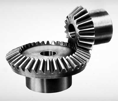
What are miter gears and how are they used?Miter gears are a type of bevel gears that have equal numbers of teeth and are used to transmit motion and power between intersecting shafts. Here’s a detailed explanation: 1. Gear Design: Miter gears have a conical shape with teeth cut at an angle of 90 degrees to the gear’s face. The teeth are cut in a straight manner, similar to spur gears, but instead of being parallel to the gear’s axis, they are cut at a right angle to transmit motion between intersecting shafts. 2. Intersecting Shafts: Miter gears are primarily used to transmit power and motion between two shafts that intersect at a 90-degree angle. The gear’s conical shape allows the teeth to mesh correctly when the shafts are perpendicular to each other. 3. Change of Shaft Direction: Miter gears are commonly used to change the direction of rotation between intersecting shafts. By meshing the teeth of two miter gears, the input shaft’s rotational motion can be transferred to the output shaft at a 90-degree angle, effectively changing the direction of rotation. 4. Speed Reduction or Increase: Depending on the arrangement of the miter gears, they can be used to achieve speed reduction or speed increase. By using different numbers of teeth on the miter gears or combining them with other gears, such as spur gears, the rotational speed can be adjusted to match the desired output speed. 5. Compact Design: Miter gears are known for their compact design, making them suitable for applications where space is limited. The intersecting shafts and the conical shape of the gears allow for efficient power transmission while occupying a small footprint. 6. Applications: Miter gears find applications in various industries and devices, including:
In summary, miter gears are bevel gears with equal numbers of teeth that are used to transmit motion and power between intersecting shafts at a 90-degree angle. They are commonly employed to change the direction of rotation, achieve speed reduction or increase, and maintain a compact design in various mechanical systems.
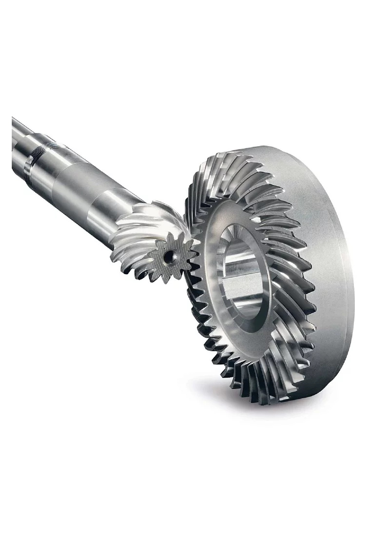
China Good quality Involute Spiral Drive Precision Transmission Wheel CZPT Angle Miter Helical Bevel Gear gear patrolProduct Description
Product Description Involute Spiral Drive Precision Transmission Wheel CHINAMFG angle Miter helical Bevel Gear
Production management: 1. The workers are trained to inspect the gears and notice any defect in production in time. QUALITY CONTROL PROCESS: Service: 1. Molds designs as per customers’ gears drawing; Packing and shipment: 1. Gears are well and carefully packed in PP bags in CTNS, strong enough for express shipping, air shipment or sea shipment. FAQ Q1: How to guarantee the Quality of gears and parts? Q2: What are the Advantage of your gears and parts? Q3: what are our machining equipments? Q4: What shipping ways do you use? 5: What materials can you process? Q6: How long is the Delivery for Your gears and parts?
What are the limitations of using miter gears in certain applications?Miter gears, like any other mechanical component, have certain limitations that may restrict their use in certain applications. While miter gears are versatile and widely used, it’s important to consider their limitations to ensure proper selection and application. Here are some limitations of using miter gears:
Despite these limitations, miter gears continue to be widely used in various applications where their unique characteristics and advantages outweigh the drawbacks. It’s important to carefully evaluate the specific requirements of the application and consider alternative gear options if the limitations of miter gears pose significant challenges.
What are the variations in miter gear designs and configurations?Miter gears come in various designs and configurations to suit different application requirements. Here are some common variations: 1. Straight Bevel Gears: Straight bevel gears are the most basic type of miter gears. They have straight teeth that are cut along the cone surface. Straight bevel gears are widely used and offer efficient power transmission, but they generate more noise and vibration compared to other designs. 2. Spiral Bevel Gears: Spiral bevel gears have curved teeth that are cut in a spiral pattern along the cone surface. This design helps to reduce noise and vibration, improves load distribution, and provides smoother operation compared to straight bevel gears. Spiral bevel gears are commonly used in high-performance applications. 3. Zerol Bevel Gears: Zerol bevel gears are similar to spiral bevel gears but have curved teeth with a spiral angle of zero degrees. This results in the teeth being parallel to the gear axis at the point of contact. Zerol bevel gears offer advantages such as reduced tooth thrust, improved tooth strength, and smoother meshing compared to other designs. 4. Hypoid Gears: Hypoid gears are a variation of miter gears that have non-intersecting and offset axes. The axes of the gears do not intersect but are positioned at an angle to each other. Hypoid gears are commonly used in applications where high torque transmission is required, such as automotive differentials. 5. Skew Bevel Gears: Skew bevel gears have teeth that are cut at an angle to the gear axis, resulting in a skewed or helical appearance. This design reduces noise, increases tooth contact area, and improves load distribution. Skew bevel gears are often used in applications where smooth and quiet operation is critical. 6. Offset Miter Gears: Offset miter gears are used when the input and output shafts need to be offset from each other. They have specific tooth profiles to accommodate the offset arrangement while maintaining proper meshing and transmission of rotational motion. Offset miter gears are commonly found in machinery where space constraints or specific design requirements exist. 7. Customized Designs: In addition to these variations, miter gears can be customized to meet specific application needs. This may involve modifications to the tooth profile, pitch angle, tooth size, or other parameters to optimize gear performance for a particular use case. In summary, miter gears offer various design and configuration variations, including straight bevel gears, spiral bevel gears, zerol bevel gears, hypoid gears, skew bevel gears, offset miter gears, and customized designs. Each variation has unique characteristics that make it suitable for different applications, allowing for flexibility and adaptability in gear system design.
How do miter gears differ from other types of gears?Miter gears possess distinct characteristics that set them apart from other types of gears. Here’s a detailed explanation: 1. Shape and Tooth Orientation: Miter gears have a conical shape with teeth cut at a 90-degree angle to the gear’s face. This differs from other gears, such as spur gears or helical gears, which have cylindrical or helical tooth profiles. The conical shape of miter gears allows them to transmit motion between intersecting shafts at a right angle. 2. Shaft Arrangement: Miter gears are specifically designed for transmitting power and motion between intersecting shafts. They are suitable for applications where the shafts intersect at a 90-degree angle. In contrast, other types of gears, such as spur gears or worm gears, are typically used for parallel or non-intersecting shafts. 3. Direction of Rotation: One of the primary differences lies in the capability of miter gears to change the direction of rotation. By meshing two miter gears, the input rotational motion can be redirected at a 90-degree angle. This is in contrast to other gears that primarily transmit motion in the same direction as the input. 4. Speed Reduction or Increase: Miter gears can be used to achieve speed reduction or increase by varying the number of teeth on the gears or combining them with other gears. This allows for adjusting the rotational speed to match the desired output speed. In contrast, other gears may have different mechanisms, such as helical gears with inclined teeth for smooth and quiet operation or worm gears for high speed reduction. 5. Compact Design: Miter gears are known for their compact design. The intersecting shafts and the conical shape of the gears enable efficient power transmission while occupying minimal space. This compactness is particularly advantageous in applications where size and weight constraints are critical factors. 6. Application-Specific Use: Miter gears find specific applications where the requirement is to change the direction of rotation between intersecting shafts at a 90-degree angle. They are commonly used in power transmission systems, automotive differentials, mechanical clocks, robotics, printing machinery, woodworking tools, camera lenses, and other devices. In summary, miter gears differ from other types of gears in terms of their conical shape, suitability for intersecting shafts at a 90-degree angle, ability to change the direction of rotation, capability for speed reduction or increase, compact design, and application-specific use. These unique characteristics make miter gears valuable in various mechanical systems where specific motion transmission requirements need to be met.
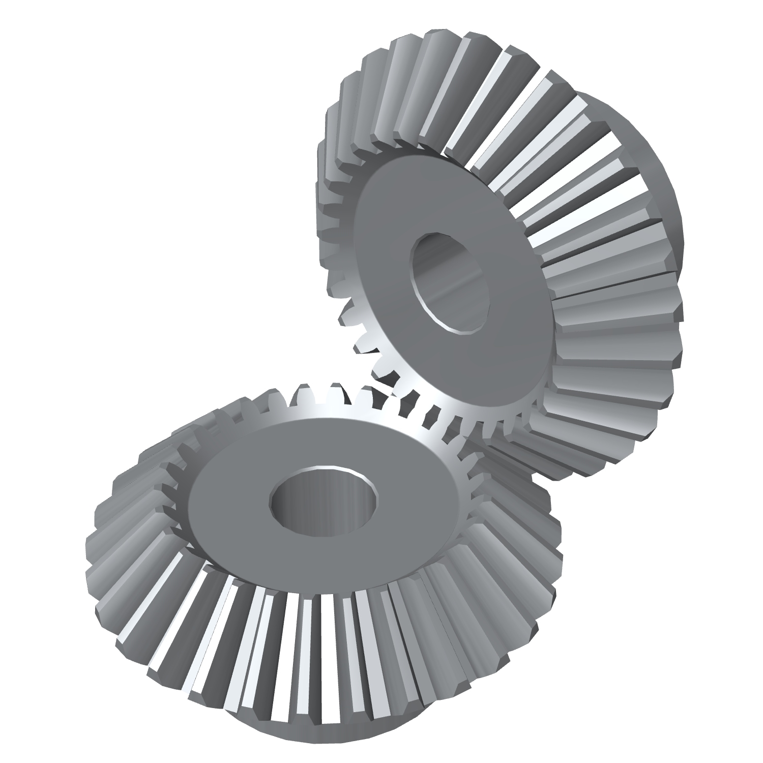
China Custom Miniature Small Helical Stainless Steel Sintered Metal Plastic Spiral Miter Straight 90 Degree Forged Straight Zerol Forging Bevel Gear Gears straight bevel gearProduct Description
miniature small helical Stainless Steel Sintered Metal plastic spiral miter straight 90 degree Forged straight zerol forging bevel gear gears Application of bevel gear Bevel gears are used in a wide variety of applications, including:
Bevel gears are an essential part of many machines and devices. They help to ensure that the rotating shafts operate smoothly and efficiently. Here are some of the advantages of using bevel gears:
Here are some of the disadvantages of using bevel gears:
Overall, bevel gears are a versatile and reliable type of gear that can be used in a wide variety of applications. They offer a number of advantages over other types of gears, but they also have some disadvantages. The best type of bevel gear for a particular application will depend on the specific requirements of that application.
What are the factors to consider when selecting miter gears for an application?When selecting miter gears for an application, several factors need to be taken into consideration to ensure optimal performance and compatibility. Here are some key factors to consider: 1. Load Requirements: Determine the magnitude and type of load that the miter gears will be subjected to. Consider factors such as torque, speed, and direction of rotation. This information helps in selecting miter gears with the appropriate load capacity and tooth strength to handle the application’s requirements. 2. Gear Ratio: Identify the desired gear ratio, which is the ratio of the number of teeth between the input and output gears. The gear ratio determines the speed and torque relationship between the gears. Select miter gears with a gear ratio that meets the specific speed and torque requirements of the application. 3. Accuracy and Precision: Determine the required level of accuracy and precision for the application. Certain applications, such as precision instruments or robotics, may require miter gears with high precision and low backlash to ensure accurate motion transmission. 4. Space Constraints: Evaluate the available space for the miter gears within the system. Consider the gear dimensions, shaft orientations, and clearance requirements. Choose miter gears that can fit within the available space while still allowing for proper meshing and alignment. 5. Noise and Vibration: Consider the acceptable levels of noise and vibration for the application. Spiral bevel gears, for example, are known to reduce noise and vibration compared to straight bevel gears. Select miter gears with suitable tooth profiles and designs to minimize noise and vibration if required. 6. Lubrication and Maintenance: Assess the lubrication and maintenance requirements of the miter gears. Some miter gears may require specific lubrication methods or periodic maintenance. Consider the ease of access for lubrication and maintenance tasks when selecting miter gears. 7. Environmental Factors: Take into account the environmental conditions in which the miter gears will operate. Factors such as temperature extremes, moisture, dust, chemicals, or exposure to corrosive substances can impact gear performance. Choose miter gears that are suitable for the specific environmental conditions of the application. 8. Cost and Availability: Consider the cost and availability of the miter gears. Evaluate the overall value proposition, including the initial cost, long-term maintenance costs, and the availability of spare parts. Balance the cost factor with the desired performance and reliability. By considering these factors, engineers and designers can select miter gears that are well-suited for the application’s requirements, ensuring efficient and reliable operation. “` How do you calculate the gear ratio in a miter gear assembly?The gear ratio in a miter gear assembly can be calculated by considering the number of teeth on the gears involved. Here’s a step-by-step explanation: 1. Determine the Number of Teeth: Identify the number of teeth on both the driving gear (input gear) and the driven gear (output gear) in the miter gear assembly. The number of teeth can usually be found in the gear specifications or by physically counting the teeth. 2. Calculate the Gear Ratio: To calculate the gear ratio, divide the number of teeth on the driven gear (output gear) by the number of teeth on the driving gear (input gear). The formula for calculating the gear ratio is:
3. Simplify the Ratio (Optional): If the resulting gear ratio is a fraction, it can be simplified to its simplest form. Divide both the numerator and the denominator by their greatest common divisor to simplify the ratio. 4. Interpret the Gear Ratio: The gear ratio indicates the relationship between the rotational speed or angular velocity of the driving gear and the driven gear. It represents how many times the driven gear rotates for each rotation of the driving gear. For example, a gear ratio of 2:1 means that the driven gear rotates twice for every rotation of the driving gear. 5. Consider the Significance: The gear ratio has practical implications in determining the mechanical advantage and speed reduction/amplification in a miter gear assembly. A gear ratio greater than 1 indicates a speed reduction and increased torque, while a gear ratio less than 1 indicates a speed amplification and decreased torque. In summary, the gear ratio in a miter gear assembly is calculated by dividing the number of teeth on the driven gear by the number of teeth on the driving gear. This ratio represents the relationship between the rotational speeds of the gears and provides insights into the mechanical advantage and speed transformation in the gear assembly.
Can you explain the unique design of miter gear teeth?The design of miter gear teeth is distinct and plays a crucial role in the functionality of these gears. Here’s a detailed explanation: 1. Tooth Shape: Miter gear teeth have a straight shape, similar to spur gears. However, unlike spur gears where the teeth are parallel to the gear axis, miter gear teeth are cut at a right angle to the gear’s face. This allows the teeth to engage correctly when two miter gears mesh together at a 90-degree angle. 2. Equal Number of Teeth: Miter gears have an equal number of teeth on both gears in a pair. This ensures proper meshing and smooth transmission of rotational motion between the gears. The equal number of teeth is essential for maintaining a constant speed ratio and preventing any slippage or irregular motion. 3. Conical Shape: Another unique aspect of miter gear teeth is the conical shape of the gears themselves. The teeth are cut on the conical surface, which allows for proper engagement and transmission of motion between intersecting shafts. The conical shape ensures that the teeth mesh correctly, providing efficient power transmission at the desired angle. 4. Meshing at 90-Degree Angle: Miter gears are designed to mesh at a 90-degree angle, allowing for power transmission between intersecting shafts. The teeth are specifically cut to facilitate this arrangement, ensuring that the gears engage smoothly and transmit rotational motion without any loss or disruption. 5. Tooth Contact and Load Distribution: When miter gears mesh, the contact between the teeth occurs along a single line, known as the line of contact. This concentrated contact area enables effective load distribution and ensures that the gear teeth bear the transmitted torque evenly. Proper tooth contact is vital for minimizing wear and maintaining the longevity of the gears. 6. Lubrication and Noise Reduction: The unique design of miter gear teeth can influence lubrication and noise levels. Adequate lubrication is essential to reduce friction and wear between the teeth during operation. Additionally, the straight tooth profile of miter gears tends to produce more noise compared to gears with helical or curved teeth. Proper lubrication and noise reduction measures are often employed to optimize the performance of miter gears. In summary, the unique design of miter gear teeth includes their straight shape, equal number of teeth, conical shape of the gears, meshing at a 90-degree angle, tooth contact along a line, and considerations for lubrication and noise reduction. These design features ensure efficient power transmission, proper load distribution, and reliable operation in mechanical systems that utilize miter gears.
China Hot selling Sintered Metal Bevel Gear 90 Degree Miter Spiral Supplyer Forged Plastic Sintered Metal Stainless Steel for Test Machine High Quanlity Sintered Metal Bevel Gear with Hot sellingProduct Description
Sintered Metal Bevel Gear 90 Degree Miter Spiral Supplyer Forged Plastic Sintered Metal Stainless Steel for Test Machine High Quanlity Sintered Metal Bevel Gear Application of Sintered Metal Bevel Gear Sintered metal bevel gears are used in a wide variety of applications where high strength, durability, and efficiency are required. Some common applications include:
Sintered metal bevel gears offer a number of advantages over other types of gears, including:
Sintered metal bevel gears are a versatile and reliable type of gear. They are available in a wide range of sizes and materials to meet the needs of different applications.
Can miter gears be used in precision machinery and equipment?Miter gears can indeed be used in precision machinery and equipment. Miter gears are a type of bevel gears that transmit rotational motion between intersecting shafts at a 90-degree angle. Their design and construction make them suitable for various applications, including those requiring precision. Here are some reasons why miter gears are suitable for precision machinery and equipment:
However, it’s important to consider the specific requirements of the precision machinery or equipment when selecting miter gears. Factors such as load capacity, speed, lubrication, and maintenance should be taken into account to ensure optimal performance and longevity. In conclusion, miter gears can be successfully used in precision machinery and equipment, offering accuracy, compactness, efficiency, and smooth operation when appropriately applied and integrated into the system.
What is the role of the pitch angle in miter gear design?In miter gear design, the pitch angle plays a significant role in determining the characteristics and performance of the gears. Here’s an explanation of its role: 1. Definition of Pitch Angle: The pitch angle in miter gear design refers to the angle between the gear’s tooth face and a plane perpendicular to the gear’s axis. It is typically denoted by the Greek letter “β” (beta). The pitch angle determines the shape and orientation of the gear teeth. 2. Tooth Profile: The pitch angle influences the tooth profile of miter gears. By altering the pitch angle, the shape, size, and thickness of the gear teeth can be adjusted. Different pitch angles result in variations in the tooth geometry, such as tooth thickness, tooth height, and the angle of the tooth face. 3. Contact Ratio: The pitch angle affects the contact ratio between the gear teeth. The contact ratio refers to the number of teeth in contact at any given moment during the rotation of the gears. An appropriate pitch angle helps optimize the contact ratio, ensuring sufficient tooth engagement and load distribution across the gear surfaces. This contributes to smoother operation, reduced noise, and improved gear life. 4. Strength and Load Distribution: The pitch angle influences the strength and load distribution capabilities of miter gears. A proper pitch angle ensures optimal load transmission across the gear teeth, preventing concentrated stresses and reducing the risk of tooth failure or breakage. By selecting the appropriate pitch angle, designers can achieve the desired strength and load-carrying capacity for the specific application. 5. Gear Efficiency: The pitch angle also affects the efficiency of miter gears. By considering factors such as tooth contact, sliding friction, and tooth deflection, the pitch angle can be optimized to minimize energy losses during gear meshing. Efficient gear design with an appropriate pitch angle contributes to higher overall system efficiency and reduced power consumption. 6. Noise and Vibration: The pitch angle plays a role in determining the noise and vibration characteristics of miter gears. Improper pitch angles can result in undesirable effects, such as excessive noise, vibration, and tooth impact. By carefully selecting the pitch angle, gear designers can minimize these effects, leading to quieter operation and improved gear performance. 7. Meshing Compatibility: When using miter gears in pairs, the pitch angles of both gears should be compatible to ensure proper meshing and smooth operation. The pitch angles need to be designed and manufactured with precision to ensure accurate alignment and optimal tooth engagement. In summary, the pitch angle in miter gear design influences the tooth profile, contact ratio, strength and load distribution, gear efficiency, noise and vibration characteristics, and meshing compatibility. By selecting an appropriate pitch angle, gear designers can achieve the desired performance, durability, and efficiency for specific applications.
What industries commonly use miter gears in their applications?Miter gears are widely employed in various industries due to their unique characteristics and advantages. Here are some industries that commonly use miter gears in their applications: 1. Automotive Industry: In the automotive industry, miter gears are commonly found in differentials. Differentials are responsible for distributing torque between the wheels, allowing them to rotate at different speeds during cornering. Miter gears play a crucial role in transmitting power from the driveshaft to the wheels at a right angle, enabling efficient torque distribution. 2. Robotics: Miter gears are extensively used in robotics for transmitting power and motion between intersecting shafts. Robots often require changes in the direction of rotation, and miter gears enable smooth and efficient redirection of power at a 90-degree angle. They find applications in robotic arms, grippers, and various other robotic mechanisms. 3. Manufacturing and Machinery: Miter gears are utilized in manufacturing and machinery for power transmission and speed adjustment. They find applications in various types of machinery such as printing machinery, woodworking tools, and conveyor systems. Miter gears allow for efficient transmission of power between perpendicular axes, enabling the precise and controlled operation of these machines. 4. Aerospace and Defense: In the aerospace and defense industries, miter gears are employed in various applications. They are used in aircraft engines, navigation systems, weapon systems, and other critical mechanisms. Miter gears provide reliable power transmission and direction changes in space-constrained environments. 5. Marine Industry: Miter gears find applications in the marine industry for transmitting power and motion between intersecting shafts on boats, ships, and other watercraft. They are used in propulsion systems, steering mechanisms, and other marine equipment that require changes in shaft direction. 6. Camera and Optics: Miter gears are utilized in camera lenses and other optical equipment to change the direction of rotational motion. They enable precise adjustment of focus, zoom, and other lens functions. Miter gears help ensure accurate alignment and smooth operation in optical systems. 7. Other Applications: In addition to the industries mentioned above, miter gears are also found in applications such as mechanical clocks, medical devices, agricultural machinery, and more. Their versatility and ability to transmit power at a right angle make them suitable for diverse mechanical systems. In summary, miter gears are commonly used in industries such as automotive, robotics, manufacturing and machinery, aerospace and defense, marine, camera and optics, as well as in various other applications. The unique capabilities of miter gears make them valuable for efficient power transmission and direction changes in a wide range of industries and mechanical systems.
|